
- #Stm32 blue pill schematic pdf how to
- #Stm32 blue pill schematic pdf install
- #Stm32 blue pill schematic pdf serial
- #Stm32 blue pill schematic pdf download
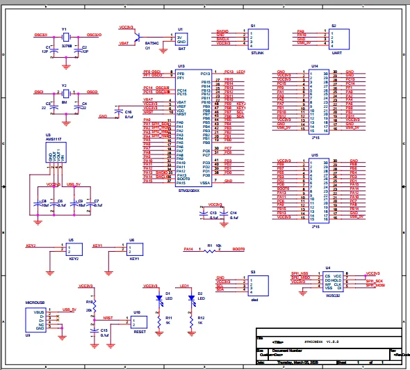
Do not power the development board from other source or USB port! It will get its power from the programmer. Connect them using the included jumper cables that came with the ST-Link. The connection to the development board is straightforward, using SWCLK, SWDIO, GND and 3.3V pins. I will be using a ST-Link v2 clone to burn the bootloader.
#Stm32 blue pill schematic pdf install
Install it.Īrduino IDE, Boards Manager - install new boardīefore actually uploading sketches to the board via USB port, it needs the STM32duino bootloader.

If your board uses a different chipset (i.e. In the dialog that appears, search for STM32 and choose STM32F1xx for "blue pill". Next, go to Tools - Boards - Boards Manager. Launch Arduino IDE, go to File - Preferences, and add the following Boards Manager URL: This step is common to all operating systems, so let's do it now. The IDE doesn't come with default support for STM32 boards.
#Stm32 blue pill schematic pdf download
Download the bootloader for your board and keep reading. If your board has the green LED connected at PC13, you need the bootloader built for this configuration: generic_boot20_pc13.bin. Roger Clark offers many bootloaders for different boards. Go to STM32duino GitHub repo and look for the bootloader. Depending on this you will choose the correct bootloader. Just solder the resistor between PA12 and 3.3V pinheader pads.Īnother thing that is good to know, is what pin the LED connects to. Don't worry, you don't have to do SMD soldering as D+ is connected to PA12. If it's 4.7 k (marked 472), a 2.2 k resistor is suitable for parallel connection. If it's 10 k (marked 103) you can add 1.8 k parallel resistor to obtain 1.5 k equivalent resistance. Look on the back of the board and locate R10. Even though my computer recognized the USB device and so may yours, I highly recommend pulling up D+ with 1.5 k if you use USB port. Also some of them have USB D+ pulled up with 4.7 k or 10 k resistors which may cause the USB port not to work on some computers. STM32duino wiki contributors have reported that some of the boards came with poor soldering of the micro-USB connector. You have access to multiple frameworks if you go for PlatformIO.
#Stm32 blue pill schematic pdf how to
If you prefer a different IDE, see here how to develop for STM32 in PlatformIO. If you decide to use ST-Link programmer, there is no need for a bootloader. Please follow instructions from Program "blue pill" with STM32 Cores in Arduino IDE. It is recommended to use that one instead. Important! There is now an officially developed Arduino STM32 boards package from STMicroelectronics.

The instructions below are based on STM32duino wiki documentation. This post will show a straightforward guide for setting up this board to work with Arduino IDE on Linux and Windows. There are also some small hardware issues with Chinese boards that need to be fixed.

#Stm32 blue pill schematic pdf serial
This can be done via serial port or using the debug interface of the MCU with ST-Link tool. But before this, an Arduino-like bootloader must be flashed to the board. Programming the board can be simplified using the popular Arduino IDE. It runs at 3.3V, but some of its pins are 5V tolerant. The microcontroller (MCU) has USB port, two serial ports, 16 bit PWM pins and 12 bit ADC pins. More than that, STM32F103 is a device with Cortex-M3 ARM CPU that runs at 72 MHz, 20 kB of RAM and 64 or 128 kB of flash memory. Although it is less popular, the board is cheaper than the Arduino Nano. The "blue pill" is a STM32F103 based development board. How to configure STM32 "blue pill" development boards for programming with Arduino IDE.


 0 kommentar(er)
